Raspberry Pi does not have a built-in ADC. Which means an external ADC has to be used to capture analog signals.
In theory, it is possible to capture certain analog signals via the audio input jack, but there may be limitations on the signal amplitude and frequency ranges, among other issues.
MCP3008 is an 8 channel 10 bit ADC from Microchip. It has an SPI interface and is very easy to use for analog input signal applications. In this article, I will show how you can interface MCP3008 with Raspberry Pi using the hardware SPI pins on Raspberry Pi.
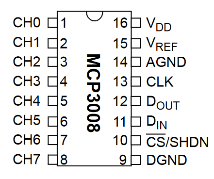
Let’s start with the connections first. The pin-out for MCP3008 is shown below:

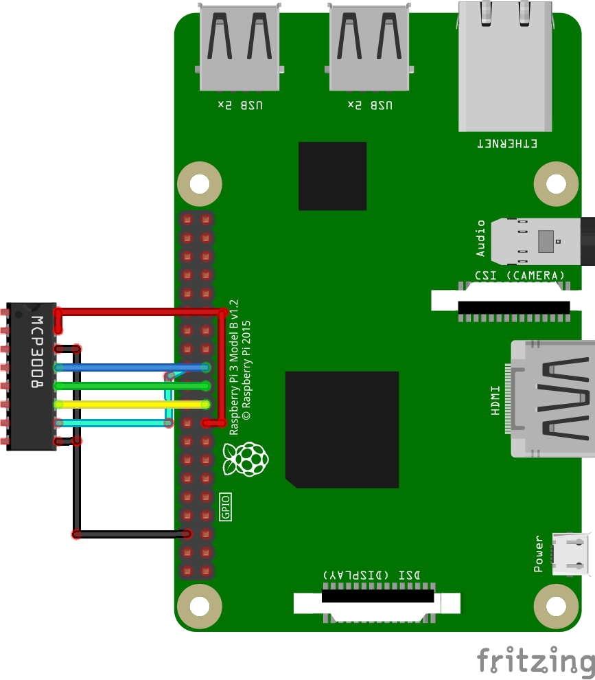
The connections with Raspberry Pi are as under (created using Fritzing):
VDD & VREF -> RPi 3.3V
AGND & DGND -> RPi GND
CLK -> RPi SCLK (GPIO11, Pin#23)
DOUT -> RPi MISO (GPIO9, Pin#21)
DIN -> RPi MOSI (GPIO10, Pin#19)
CS/SHDN -> RPi CE0 (GPIO8, pin#24)

I used the Adafruit CircuitPython library for the MCP3xxx series of analog-to-digital converters for the communication code. To be able to run the code below, you’ll need to run something along the lines of (depending on your Python version):
pip3 install adafruit-circuitpython-mcp3xxx
A simple Python script (taken from CircuitPython examples) can be used to verify that MCP3008 works as expected. You do not need to connect any input signal to MCP3008 to test the basic operation, but you can if you have a signal source.
import time
import busio
import digitalio
import board
import adafruit_mcp3xxx.mcp3008 as MCP
from adafruit_mcp3xxx.analog_in import AnalogIn

# create the spi bus object
spi = busio.SPI(clock=board.SCK, MISO=board.MISO, MOSI=board.MOSI)

# create the cs object
cs = digitalio.DigitalInOut(board.D5)

# create the mcp object
mcp = MCP.MCP3008(spi, cs)

# create an analog input channel on MCP3008 pin 0
chan = AnalogIn(mcp, MCP.P0)

while True:
  print('Raw ADC Value: ', chan.value)
  print('ADC Voltage: ' + str(chan.voltage) + 'V')
  time.sleep(0.1)
Output:

